Использование экспортёра XSI
Материал из CryWiki Russia
Содержание |
Использование экспортера SOFTIMAGE|XSI
Введение
CryExporter это дополнение для программы XSI, в котором кроме полноценного функционала экспорта, есть ещё набор объектов и собственный шейдер для достижения максимального эффекта использования мощи CryENGINE2. The CryExporter prepares assets created in Softimage XSI for the CryENGINE2 Resource Compiler (RC). The assets are stored in the Collada format and within the RC converted to the final game asset.
What is new in this version?
- Support for .chr + .caf: weighted meshes, deformation hierarchies, animations
- Support for .cga + .anm: geometry hierarchies , animations
- Synced names of Menu Items and Custom Command Scripts (in order to easily create your own Toolbar)
- Cleaned up the Crytek menu: we removed functions that became irrelevant for production (Create CryHelperNode, Crytek Toolbar, various Fixing scripts)
XSI Training
For these who do not know XSI and would like to know more before they dive into the world of modding, we collected some links.
Video Tutorials about using Softimage Mod Tool or XSI 6.X:
- First contact: Softimage Forums
- Training Material: Softimage Forums
Web Sites with Tutorials
- Ed Harris: EdHarris.com
- Highend3D: XSI Tutorials
- XSIFiles: XSIFiles.com
Concept
- Every game asset that you want to export has a CryExportNode as a root Node. This node, a special model node, stores export settings and the name of the final game asset.
- A single scene can contain more then one game asset.
- Link the geometry and its functional parts to the CryExportNode.
- Export one or all CryExportNodes from XSI the resource compiler will create the target files automatically.
- Plot animations for animated hierarchies into XSI Action clips and export them as anm or caf.
- Create and export characters with deformation rigs (including vertex weighting information)
Possible types of assets which can be set up in an XSI scene:
- static rigid geometry (i.e. buildings) (.CGF)
- linked hierarchies of geometry objects (.CGA) and animations (.ANM)
- characters skinned to a geometry hierarchy (.CHR) and animations (.CAF)
- material libraries (.mtl)
Exported Data
- 3D rendering mesh
- UV data
- Vertex colors
- Hierarchical structures (linked geometry or skeletons)
- Pivot position
- Helper Nodes
- Scaling information
- Material assignment
- Collision properties for polygons
- Envelope weights
- Custom text properties (i.e. mass, density, rotational limits)
UI
Crytek Menu
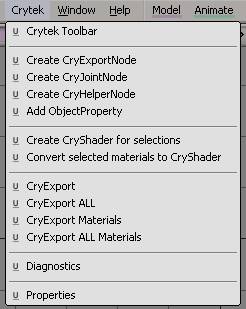
After the installation of the Crytek Addon, you will find the Crytek menu in the XSI menu bar.
Nodes
Create CryExportNode
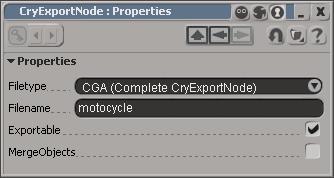
Creating a CryExportNode model automatically triggers the "CryExportNode: Properties" window, where you need to specify various parameters for the final asset.
You can choose the type of asset, i.e. .cgf, .cga or .chr file. The name of the final asset is also specified here. The filename will then be added as a prefix to the CryExportNode name. i.e. motorcycle_CryExportNode.
Additionally you can choose whether this particular asset should be exported during when using the Export all command (this is useful for test objects). Check merge, if the asset has no internal logic attached and is composed of many separate geometry nodes. The exporter will automatically remove the hierarchy and compress the data for the target asset. This might save a lot of rendering and processing time. The values are stored in custom properties called ExportProperties . You can easily access them from the Explorer.
Примечание:
Select the object in XSI and press F3. This will bring up a MiniExplorer, tailored for the selection.
Create CryJointNode
This node is a box shaped null helper which serves as a joint in your object. The Default name is CryJointNode. Link it to the CryExportNode model. The joint needs to be placed between two geometry nodes, so that its bounding box is intersecting with the bounding box of the two objects it should keep together. The null has a text property in which you can adjust the physical parameters for the joint, i.e. limit=10000
Joint parameters:
- limit = <value> (Joint object property) - limit is a general value for several different kind of forces applied to the joint. It contains a combination of the values that define the forces applied to the different axis.
Примечание:
This value needs to be defined; otherwise the simulation will not work correctly. Crysis Example values: 100 - 500 can be broken by a bullet; 10000 can be broken by the impact of a driving vehicle or a big explosion.
The following values are optional and are used to fine tune the "limit" settings.
- bend = <value> (Joint object property) - maximum torque around an axis perpendicular to the normal.
- twist = <value> (Joint object property) - maximum torque around the normal
- pull = <value> (Joint object property) - maximum force applied to the joint's 1st object against the joint normal (the parts are "pulled together" as a reaction to external forces pulling them apart)
- push = <value> (Joint object property) - maximum force applied to the joint's 1st object (i.e. the one whose name is listed first in the joint's name, or if the names were not specified, the object the joint's z axis points towards) along the joint normal; joint normal is the joint's z axis, so for this value to actually be "push apart" (as a reaction to external forces pressing the parts together), this axis must be directed inside the 1st object
- shift = <value> (Joint object property) - maximum force in the direction perpendicular to normal
Примечание:
Joints also support non-fully-rigid (non-6dof) constraints. A full rigid constraint will become a dynamic constraint if its either bend and twist limit gets broken and the joint has a non-0 "constraint_limit" property. Broken "bends" will become "socket" constraints, and "twists" will become hinges. The newly created dynamic constraint will inherit pull and shift limits from the joint. The constraint's frame will be that of the joint's helper in max. In order to preserve the meaning of "twisting", however, the axes will be swapped (z of the joint's helper will become the constraint's x - since both represent the "twising" axis, x will become y, and y wil become z). Thus, for hinges, z asis of the helper should be directed along the desired hinge direction. For socket's, z axis should be the axis the attached part "bends around".
Fully-rigid (non-6dof) constraints related properties:
- constraint_limit = <value> (Joint object property) - Force limit for the newly created constraint, is checked when the constraint hits a rotation limit and is being pushed further
- constraint_minang = <value> (Joint object property)
- constraint_maxang = <value> (Joint object property) - Rotation limits for the constraint (the interpretation is the same as in standalone constraints). The default is no limits
- constraint_damping = <value> (Joint object property) - Angular damping (default 0)
- constraint_collides = <value> (Joint object property) - Whether the constraint parts will ignore collisions with each other (default 1)
For example, to quickly create an unbreakable hinge constraint, add the following values to the joint's properties:
- twist = 0 - The constraint will created at the first activation, regardless of force.
- constraint_limit = 1E20 (just something big enough)
Note that the general "_limit = xx_" is not required, since we want the limits other than twist to remain unbreakable. Also note that the nodes that have dynamic constraints between them should always be physicalized as entities (not particles).
Create CryObjectProperty
Create ObjectProperty adds custom properties (text field) to your node. Use this function to add values to the node a to a geometry node. It enables you to add engine properties to a node, like mass/density, LowSpec Settings, etc.
ObjectProperty settings:
- Mass = <value> defines the mass in kilograms; do not use together with density; i.e. mass=50
- Density = <value> - numerically defines the density of the material, the mass will be calculated based on the volume of the bounding box, i.e density=2
- Pieces = <names> - defines the name of pieces that are spawned (and replaces the original object) when a physical impulse on a joint exceeds its limits, i.e. pieces=_wall01_piece01,_wall01_piece02,_wall01_part
- LowSpecLod0 - identifies the object as the base lod on a lowspec machine, i.e in the properties of a Lod1 or Lod2
- Entity - turns a piece into an entity, which the player can interact with.
- Count= <value> - spawns the piece object x-times, i.e. count=50 spawns 50 pieces within the volume of the intact object
- Name= <name in engine> - use it in case scripts need a name, which XSI does not support, like SPACE in the name. i.e. name=Bip01 R Hand
Character specific Object properties - IK setup for deformation rigs:
- xmin = <value> limit of negative rotation on X-axis
- xmax = <value> limit of positive rotation on X-axis
- ymin = <value> limit of negative rotation on Y-axis
- ymax = <value> limit of positive rotation on Y-axis
- zmin = <value> limit of negative rotation on Z-axis
- zmax = <value> limit of positive rotation on Z-axis
All values are relative values to the default joint rotation of the phys skeleton. You can also change the rotation of the phys skeleton compared to the deformation mesh in order to get a higher range of motion. As a general rule of thumb for the rotational limits, you should keep max >min and respect the following limits X, Y -180 180 and z -90 90. Better keep the range of limit smaller than the maximal values given (i.e. 170 to -170). This ensures stability in the physics calculation.
The following values are used to fine tune the behavior of joints. Most of the time they can be neglected, though. Dampening and Spring Tension Stiffness of an angular spring at a joint can be adjusted via "Spring Tension" parameter. A value of 1 means acceleration of 1 radian/second2 (1 radian = 57). Damping should also be set to some reasonable value (1.0 corresponds to fully dumped oscillations for an isolated joint, 1.0 is the recommended value ). The Spring Angle can also be adjusted, but has not much influence therefore we recommend to keep it at 0 (just included for legacy reasons).
- xdamping = <value>
- xspringangle = 0
- xspringtension = <value>
- ydamping = <value>
- yspringangle = 0
- yspringtension = <value>
- zdamping = <value>
- zspringangle = 0
- zspringtension = <value>
Shader & Material Setup
CryShader
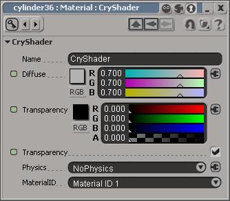
The main difference to a standard XSI shader is the addition of the Physics setup and the Material ID. The Physics setup is needed to tag polygons with physical properties. The Material ID setup should left alone; it helps the Addon to track the numbering of the assets materials.
Примечание:
The physics properties are not stored in the material file .mtl, which is being created from the material library, but only in the geometry information of the object. This is done for performance reasons.
Physics Parameters:
- NoPhysics - Default Value, the polygons are not physicalized
- Physics - the polygons are physicalized to block the player and vehicles. The assigned polygons serve as a physics and render geometry, i.e. a tree trunk
- Physics (NoDraw) - the polygons are physicalized to block the player and vehicles but are invisible. The polygons can not get a rendered shader assigned in Sandbox.
- No Collide - use this for very simple proxies that do not block the player, but are used for detecting bullet shots or player interaction. The calculation will then detect the render mesh below.
- Obstruct - the polygons are physicalized in order to block the AI view; player, AI and vehicles can pass through, i.e. used for vegetation cover objects
Material File
Separate materials are organized on material libraries. The Addon uses XSI material libraries to identify the material name for the CryENGINE2 material that is attached to the asset. i.e. if the material library is called "testCube", the Addon will create a the material file "textCube.mtl" for CryENGINE2. Therefore, one object must have its materials collected in one material library. Also remove all unused materials from the library, as they could interfere with the numbering process and they just create memory waste on your target platform.
Convert Selected Materials to CryShader
Use this function to manually convert selected materials into a CryShader material. This sets the default Physics settings (NoPhysics). Select the material in the Explorer (Keyboard Shortcut 8>M) or in the Material Manager's cluster and clip explorer.
Примечание:
The Addon automatically adds prefix numbers to the materials to keep the order of the materials consistent. XSI sorts the materials in alphabetic order. Adding new materials afterwards could mix up the order and could cause a mismatch of the materials on the object and in the already existing .mtl file.
Character Setup
This is just a primer to the topic, for more information, please refer to the Documentation of the CryWiki. There you can find the Character Creation Tutorial, which is mainly based on 3dsMax, but information can easily be transferred to XSI.
Concept
Character Definition
A character is a render mesh, with its vertices being transformed by an underlying hierarchy (skeleton). The link between vertices and the hierarchy is handled via envelopes. A character must have one deformation hierarchy and can have an optional "phys skeleton".
Deformation Skeleton
Despite using XSI bone chains to deform the render mesh, the CryExporter expects (export of bone chains is an unsupported feature), the deformation hierarchy is based on linked geometry (deformation skeleton), which can be driven via constrains by any hierarchy you like to use (animation rig). This decoupling of deformation and animation rig enables you to use all existing features of XSI for animation. The deformation skeleton should resemble roughly the shape of the render mesh, as it serves as the collision mesh (material of the deformation skeleton must have Physics turned on). The deformation skeleton can life under its own model node and can be shared between several characters. It can even be used as a referenced model.
Phys Skeleton
If live physics or dead body physics are necessary, a second hierarchy needs to be used (Phys skeleton), which contains the nodes you want to physicalize, plus the postfix "_Phys" in the node names. Every node in the phys skeleton needs to have some text properties added in order to have the rotational limits and physics behaviour set up correctly, otherwise it will not be registered by the physics part of the engine. Simple characters like boids do not need a phys skeleton.
Naming Convention
The names of the sample character are similar to the popular 3dsMax Character studio BIPED setup, plus some additional nodes for special features (Eye tracking). They were used for the creation of the original Crysis animations. Use the provided sample character to make use of these animations, as well as all the special features. If you plan to not use any Crysis animations, you can freely choose the name of your skeleton. Please refer to the documentation on the CryWiki for more information about the names for special nodes.
Blend Shapes
You can create blendshapes for your characters and export them to the engine to use them with the Facial editor. The Exporter automatically strips the postfix __ShapeKey_ from the Blendshapes's name.
Animation
CryAnimation
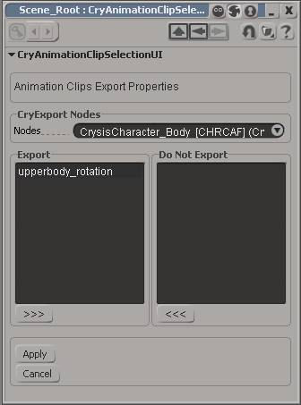
The CryAnimation window lets you toggle the export status of animation clips for a CHR or CGA object. This is useful to filter a complex set of animations for an automated export. Select the Node for which you would like to toggle animations in the requester CryExportNodes. Select the plotted animations and toggle their export status with the arrow key buttons below the list windows.
- Apply - Use Apply to confirm your changes to the exporting animations before switching to another node.
- Cancel - Use Cancel to return to the initial setup for the current node's animation export settings. Returns either to the status before the window was opened, or if you pressed Apply in the meantime, to the status you confirmed during the session.
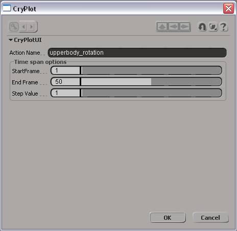
CryPlot
This function creates a plotted animation action of the selected animated nodes. It plots also all animation coming from expressions and constrains. These actions are stored in a local Mixer Node of the CryExportNode. They can be accessed through the Explorer (Mixer > Sources> Animation).
- Manually select the nodes branch or group select is not working.
- For a .cga object, you must select all children of the CryExportNode, that should have their animation stored in the action.
- On .chr objects, you need to select the deforming skeleton hierarchy, (children of the CryExportNode). Do not select the enveloped mesh.
- You can also plot the animation data for parts of the hierarchy. Make sure you always choose one top node. These animations can be used for special application, i.e. arms or upper body animations.
You need to type in the Action Name to be able to identify the Action later. If you choose an existing name, XSI will automatically add a postfix to the name. You need to identify the Start and End Frame of the animation you want to plot. These are, ideally the frames with the first and the last set keyframe. In the Step Value you can specify on which frames the plotting function should create new keyframes. Default is "1" , means every keyframe. Keyframes are created with "Constant Interpolation".
Export Sub Hierarchies
You can also export animation for parts of the hierarchy by using a naming convention in CryPlot. Using sub hierarchies is useful, if you have a walk cycle, but want to override the default arm position with a different one in which the character carries a different items. You would not need to create a completely new walk cycle and waste memory for redundant parts.
Animations for sub hierarchies are identified by a naming convention:
- _<nameofcaffile>-root-<rootbone1name>-root-<rootbone2name>_
You can specify as many roots as you like in this way. Only animations for these bones and their children will be exported. An animation clip with the name "_carryweapon-root-Upper_Arm_Left-root-Upper_Arm_Right_" would export an animation for both the arms with the name "_carryweapon.caf._" Any other parts of the skeleton are not taken into account for this animation.
Exporting
CryExport
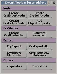
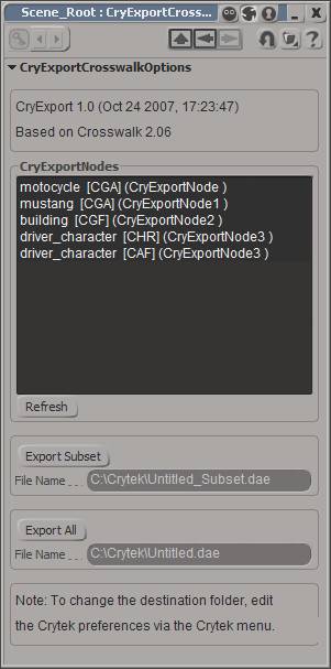
Once ready to export, the artist can open the following UI via the Crytek menu or toolbar:
All the assets and their corresponding Crytek compiler out filename and file type are listed in the CryExportNodes list. If you want to export only some assets of the scene, you can select the assets in the list and use Export Subset . The specified "<filename>_Subset.dae" COLLADA file will be exported.
- Export All creates a COLLADA file with the name you specify, containing all the assets from the scene. The RC will then create separate files in the target format.
The CryExport exporter takes into account every asset individual property and will only export the required elements for that particular asset/file type in the intermediate COLLADA file.You can also access a shortcut to the Export All function through the Crytek Menu. This save some time during the testing and learning phase.
Exported file types:
- CGF: static rigid geometry (i.e. buildings)
- CGA: linked hierarchies of geometry objects
- ANM: animations for .CGA objects
- CHR: characters skinned to a geometry hierarchy
- CAF: animations for .CHR objects
CryExport Materials
Similar to the CryExport function, this window lets you select the available material libraries and export them to the export folder. This is useful to create an initial version of the material. The fine tuning needs to happen in the Sandbox Material Editor anyway. You can choose between exporting the selected materials in the list or exporting all the materials at once. With Export all Materials , you also have a shortcut to create a material file for all the available Material libraries.
Exported file types:
- MTL: material file, taking into account the diffuse colours and texture paths. They will be created relative to the Game folder.
Additional Tools
Diagnostic
Diagnostic is a validation process, which checks various settings and properties for the selected assets. It checks for valid filenames, proper material and material library names, whether pieces are available, etc.
Vertex Colour Painting
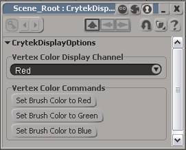
This opens a special toolbar which helps applying vertex colours for vegetation objects. It lets you review the separate vertex colour channels (R/G/B) and holds buttons to set the vertex colour to pure red (255/0/0), green (0/255/0), blue (0/0/255) colours.
Примечание:
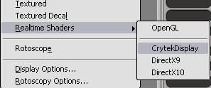
In order to make use of the mode, you need to switch to the CrytekDisplay in the Realtime Shaders selection of the Viewport.
Setup
CryProperties
The Addon needs some initial setup to work properly.
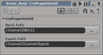
- First you need to set up the path to the Bin32 folder of your CryENGINE2 installation. This folder has a subfolder called "rc", which contains the Resource Compiler that converts the COLLADA files into CryENGINE2 binary files. This path needs to be setup once (or every time you want to test a different Resource Compiler in a different location), as it is saved in the XSICryExport preferences. (<path of Crytek Addon>/XSICryExport.xsipref).
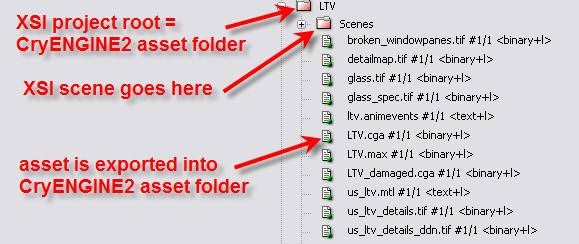
- Secondly you need to set up the export path for the assets in the current scene. The export path is saved on a per scene basis and the settings will be deleted for every New Scene you create in Softimage. CryENGINE2 assumes that 3D assets are stored within the Objects folder of your game installation or your Mod (see the example path below). We advise you to export the assets into this folder to minimize setup time.
Примечание:
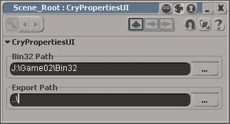
Special path setup for Export Path - Instead of using an absolute path, you can also set the path one folder up of the current scene location by using "..." as the Export path itself (see example below). This helps when exchanging assets with other modders, as it the plugin will automatically export the asset into the correct location (one folder up), if the whole asset folder was exchanged.
Softimage is organising projects in folders, but CryENGINE2 expects all relevant data for an asset in one folder (.cgf, .tif, .mtl). By using this option, you can set your project in XSI directly to the folder that contains the final game asset. XSI automatically creates subfolders and saves new scenes in the scene folder.
Special Object Setup
Occlusion Objects
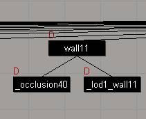
These are simple geometry objects which are placed inside non see through walls to indicate the renderer that everything behind it does not need to be rendered. This is helpful in busy scenes to ensure high render performance. The name of the geometry object needs to start with "_occlusion". Link it to the geometry object which serves as the "visual barrier" in the game.
You can check them with various console commands:
- e_cbuffer_draw_occluders 1 - debug draw of occluders in coverage buffer.
- e_debug_draw 11 - Render occlusion geometry additionally
- e_debug_draw 12 - Render occlusion geometry without render geometry
- e_debug_draw 13 - Render occlusion ammount (used during AO computations)
Pieces for Breakable Objects
Pieces geometry nodes can be placed anywhere in the hierarchy. They can be named to your liking, but need an underscore as the first character. i.e. _piece01, _wall01_part01, _blah
Branches
The branches nulls are needed for the setup of bending vegetation leafs. The nulls are used as joint in the engine, through which the physics engine interpolates a rope spline, with which the player can interact. The branches have a special and strict naming convention: branch<#>_<#> i.e. branch01_01, branch01_02, branch02_01, branch02_02, branch02_03
The system is unconventional, but very efficient. The bounding boxes of the branch nulls needs to enclose vertices which are influenced by the spline. Ideally you choose the vertices lying in the centre line of a branch (it works especially well for trees with large leafs, like palm trees). The engine then makes a lookup in the UV coordinates and checks for all vertices, which have connected UVs. All the connected vertices are taken into account when the physics calculates the deformation. The cool thing about it is, that you do not need to create weighting on the vertices and you only need to set up one () leaf and all other instances in the asset will automatically work, if they share the same UV coordinates. You can even deform the other leaves and still have the effect applied.
LODs
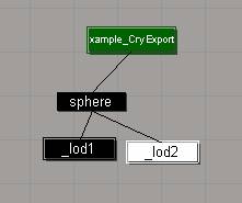
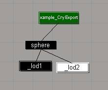
You can make use of the Level of detail functionality of CryENGINE2 by linking the LODs to the Base object, add an UNDERSCORE to the name and number them accordingly. The rule of thumb is to reduce the polycount for every LOD step by 50%. If you only remove 20% of the polygons, the LOD will not load for being insufficient. There is a exception, though. If you use less different materials than on the previous LOD level, the LOD will still work, even if there are not 50% of the polygons saved.
You can also add a postfix with the name of the LOD0 (in this case "sphere") to the name of the LODs, i.e. _lod1_sphere or _lod2_justforfun. Important are only the first 5 characters.
Exclude Assets From Export
Sometimes, nodes do not need to be in the final hierarchy, but they can help to facilitate the setup. In order to remove such nodes from the export procedure, just add the prefix "-" (minus) in front of the node name, i.e. "-helper_node". Using the prefix can also help reducing the final asset size.
Примечание:
All children linked to such a node will not be exported.
Additional Functionality
Some functions are not available anymore in the menus. They were not used often enough to justify their existence in the menu. We believe in streamlined tools.
DeleteMaxNormals
Deletes the additional set of normals being created when assets are imported from 3dsMax via Crosswalk. You need to delete these normals before exporting to CryENGINE2. This function is only accessible through a Custom Command Script. Please add it to the your toolbar or assign a keyboard shortcut to it.
