Хрупкие объекты
Материал из CryWiki Russia
Содержание |
Breakable Objects
Breakable objects consist of separate pieces which are held together by joints.
The single parts can be separately disjointed, by applying physical force (bullets, player interaction, explosions) bigger than the joint limits.
In general, Breakable objects are placed in Sandbox as brushes
A perfect example for a breakable objects would be a road sign, a wooden fence, or a wooden shag.
Table of Content
Sample File
Sample File: Breakable-Example
General Setup in 3d applications
- The objects must have several nodes in max, each with its own physics.
- Nodes are held together with joints (each joint can connect only 2 parts).
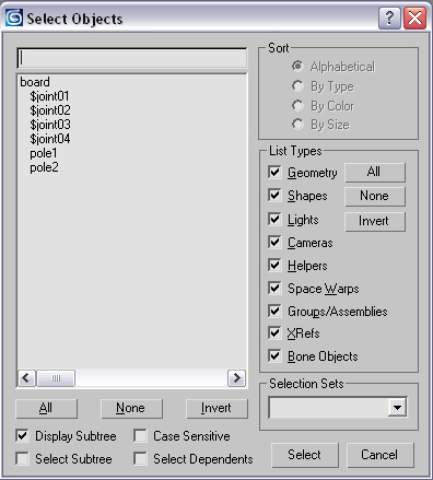
- Naming convention for Joints: $joint01, $joint02,…
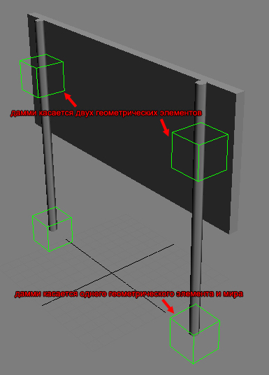
- Joints are represented in the 3d application with helper objects (dummies, Nulls..). They need to intersect with the physics proxy of 1 or max. two geometry objects.
- The Z-orientation of the joint pivot should normally point upward (see Debug section)
- Alternatively, one can explicitly specify part names in the joint name using this format: $joint1_part1_part2. This can be useful at complicated junctions where geometrical intersections can find more than 2 parts
- When a joint object intersects only with one node, a joint between the object and the world is created.
- The size of the dummy object does _not_ have any effect on the strength.
- It is, however, used to re-attach joints to broken parts if some geometries also have procedural breaking on (namely: when a part breaks procedurally, all joints that are attached to it are checked for intersections with the newly formed pieces, and are re-attached to them if needed)
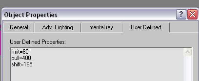
- The strength of the joints and the mass of the separate are defined in the node properties (different name in every 3d application; in 3ds: objects Properties)
- Specific joint limits are relative to the joint’s normal, represented by the helper node’s *z* axis. For joints that specify part names explicitly, care must be taken that the normal points into the 1st parts (otherwise push and pull limits will switch meanings)
- Turn OFF «Merge All Nodes» on export
- Objects can be placed as brush or geom. Entity
- example for dummy placement

- Example for joint properties

Each time an external force (from collisions with other objects, or bullet hits) is applied to the object, the system calculates internal forces needed to hold the object parts together, and if some forces breach the threshold, the corresponding joints are removed. Then part connectivities via remaining joints are recomputed and isolated islands are moved to new entities.
Node Properties
The nodes need properties attached (depending on software) to work correctly in the engine.
- entity (render geometry property)
If the render geometry properties include «entity», the object will not fade out after being disconnected from the main object.
- box (render geometry property)
If the render geometry properties include «box», the engine will use a simple box (based on the bounding box of the object’s physics proxy) as the collision geometry. This helps speeding up physics calculation.
- mass=VALUE (render geometry property)
Mass defines the weight of an object based on real world physics
mass=0 sets the object to «unmovable». This is used on the basement of a house for example or the sign pole which should not be movable and always stay in the original position. When used in brushes and Geom Entities, this is the final part’s mass. When used in regular Entities, all parts masses are scaled so that their total mass gives the mass specified in the entity properties.
- CAUTION* You must either define this value or density to ensure the simulation is working correctly.
- density=VALUE
The engine automatically calculates the mass for an object based on the density and the bounding box of an object. Can be used alternatively to mass.
- limit=VALUE (Joint object property)
limit is a general value for several different kind of forces applied to the joint. It contains a combination of the values below.
CAUTION This value needs to be defined, otherwise the simulation will not work correctly.
Crysis Example values: 100—500 can be broken by a bullet; 10000 can be broken by the impact of a driving vehicle or a big explosion.
The following values are optional and are used to fine tune the «limit» settings.
- bend=VALUE (Joint object property)
maximum torque around an axis perpendicular to the normal.
- twist=VALUE (Joint object property)
maximum torque around the normal
- pull=VALUE (Joint object property)
maximum force applied to the joint’s 1st object against the joint normal (the parts are «pulled together» as a reaction to external forces pulling them apart)
- push=VALUE (Joint object property)
maximum force applied to the joint’s 1st object (i.e. the one whose name is listed first in the joint’s name, or if the names were not specified, the object the joint’s z axis points towards) along the joint normal; joint normal is the joint’s z axis, so for this value to actually be «push apart» (as a reaction to external forces pressing the parts together), this axis must be directed inside the 1st object
- shift=VALU (Joint object property)
maximum force in the direction perpendicular to normal
Addition: joints also support non-fully-rigid (non-6dof) constraints. A full rigid constraint will become a dynamic constraint if its either bend and twist limit gets broken and the joint has a non-0 «constrant_limit» property.
Broken «bends» will become «socket» constraints, and «twists» will become hinges. The newly created dynamic constraint will inherit pull and shift limits from the joint. The constraint’s frame will be that of the joint’s helper in max. In order to preserve the meaning of «twisting», however, the axes will be swapped (z of the joint’s helper will become the constraint’s x — since both represent the «twising» axis, x will become y, and y wil become z). Thus, for hinges, z asis of the helper should be directed along the desired hinge direction. For socket’s, z axis should be the axis the attached part «bends around».
Here is the list of related properties:
- constraint_limit=VALUE (Joint object property)
Force limit for the newly created constraint, is checked when the constraint hits a rotation limit and is being pushed further
- constraint_minang=VALUE (Joint object property)
- constraint_maxang=VALUE (Joint object property)
Rotation limits for the constraint (the interpretation is the same as in standalone constraints). The default is no limits
- constraint_damping=VALUE (Joint object property)
Angular damping (default 0)
- constraint_collides=VALUE (Joint object property)
Whether the constraint parts will ignore collisions with each other (default 1)
For example, to quickly create an unbreakable hinge constraint, one should put this into the joint’s properties:
twist = 0 (the constraint will created at the first activation, regardless of force)
constraint_limit = 1E20 (just something big enough)
Note that the general «limit = xx» is not required, since we want the limits other than twist to remain unbreakable.
Also note that the nodes that have dynamic constraints between them should always be physicalized as entities (not particles).
Dissolving into particlespieces
Jointed Objects can be set up to break in smaller pieces when being detached from the joint. i.e. a wooden sheet breaks into several planks.
The object properties must contain the information about the pieces used. i.e. «pieces=$blah1», «pieces=$rock1».
Several objects can share the same name, but it is also possible to set up the pieces with different names, i.e. «pieces=$blah1,$blah2».
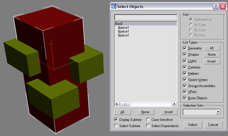
Pieces need to be linked to the object they should replace later on.
NOTE: make sure the names of the objects you want to use as pieces are in lower case only i.e. $debris or $piece1. Debris would not work.
WARNING Be aware that the search function in the code also returns nodes with only partially matching strings. If you have problems with pieces spawning out of nowhere or existing nodes being cloned for no reason, look into the name strings and change them to avoid this issue.
If you don’t specify anything in the piece properties, they will be spawned as particles, which means they will have no collision and will disappear after a few seconds. If you want the pieces to behave like actual physicalized objects, you have to add «entity» into their properties box.
- Sample setup

Practical examples of how pieces can be used:
— Optimization: If you create a dummy object with a nodraw material (like a simple cube) and spawn it as a piece, the jointed object will simply disappear once the joint breaks — it will be replaced by an invisible object. This can be helpful since the piece that is broken off will not fall down and interact with the remaining pieces, potentially causing problems, and it is also beneficial performance-wise. Once the original object is seperated from its joint, no further physics calculations will be necessary.
— Adding dynamic detail: Pieces replace their original object once this object is «broken off» (seperated from it’s joint), so you can take the original object and cut it up into smaller pieces. An example of this is the huts in crysis, most roof panels have two sub-pieces that spawn once the panel breaks off. This results in more detailed breaking and smaller debris. Don’t forget to add «entity» and a realistic mass to the piece properties, and make sure the piece is physicalized, or else the pieces will fall through the ground and/or disappear after a few seconds. (in case they are only small «fluff» pieces, this might actually be intended)
— Adding static detail: You can also spawn small debris pieces, that, instead of falling down, stay where they appear (for example steel cables sticking out of a concrete wall). To do this, you have to add the following lines to the properties of the piece:
entity
mass=0
density=0
Entity because you want the object to stay where it is once it is spawned, and because you want it to be physicalized. The object needs to be physicalized (i.e. contain polygons with a physicalized material) in order for this to work. Mass and density need to be 0 to assign the objects infinite mass, which results in the object staying where it spawns and not reacting to force. If it wasn’t 0, it would fall down upon spawning.
Level of detail settings
LodCreation per object can easily be added by naming them $lod1; $lod2, $lod3… and linking them to the relevant subobjects. In order to make differentiation easier, a postfix can be added; i.e. «$lod1_wooden plank»
Occlusion Proxy
An OcclusionProxy can be added by naming it $occlusion and linking it to the relevant jointed object; like a big sheet of metal on a metal fence or a wooden wall on a hut. Occlusion proxy is allowed to have open edges and need to be as low as possible (something around 2-10 polys).
Instancing within breakable objects
AssetCreation_InstancingObjects Instancing objects] is used to optimize render time by reducing drawcalls and memory consumption.
The engine automatically detects identical geometry elements within the exported objects.
There is no special setup needed to take advantage of this feature. UVs and relative point position to the pivot need to be identical in objects in order to qualify them for instancing.
Linking Objects to simplify export
Linked objects don’t need to be exported, just the Root node needs to be added to the exporter list. All child nodes will automatically be exported. The name and pivot will be derived from the root joint.
- Example of linking objects and joints for simpler export

Setup in Sandbox
Add the object as a brush or a Geom. Entity. In case of a brush, the engine will detext automatically that the object is breakable. For multiplayer where breaking objects has a massive impact on the data transfer, breakability is automatically disabled (might change later)
Debugging
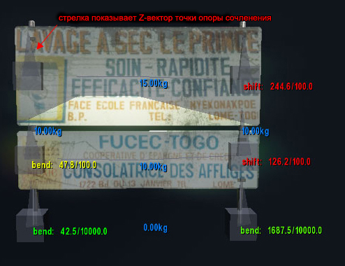
- p_debug_joints 1 shows the default debug mode for joints (see picture below); p_draw_helpers needs to be activated
- CAUTION Never scale a joint If you need a new size, create a new joint. the scaling value will be passed on to the engine and causes wrong results in the simulation.
- The «spikes» on the joint objects show the orientation. For limits to properly reflect their names (i.e. pull, twist, etc), the spikes must be directed along the «natural» joints axes. However, it’s also possible to keep them always pointing up, for consistency.
- The blue colored numbers show the mass of the single pieces. Note the «0.00kg» this is the mass of the top node — in this case a dummy.
- Joints linked to the world are displayed red.
- When a force is applied to a joint, the direction is shown (in this case shift and bend), together with the strength and the limit of the particular joint. Green text represents an impact with an impulse much lower then the joint limit. Yellow represents values closer to the joint limit. Red represents values which were higher than the limit — in this case the joint is broken.
- NOTE: the debug mode is handy to see how the impulse of weapons react with the breakable object. set the general limit first and then fine tune the specific limits by setting them explicitly for shift, bend…
- Example of debug display